کیتهای الکترونیک
|
| |
|
| |
|
| |
|
| |
|
| |
|
| |
|
| |
|
| |
|
| |
|
| |
|
| |
|
| |
|
| |
|
| |
|
| |
|
| |
|
| |
|
| |
|
| |
|
| |
|
| |
|
| |
|
| |
|
| |
|
| |
|
| |
|
| |
|
| |
|
| |


+ نوشته شده در ۱۳۸۸/۱۲/۲۱ ساعت توسط احد دانشمند
|

 | |||||||||||||||||||||||||||||||||||||||||||||||||||||
 صوتی و تصویری فلاشر , رقص نور , آنالیزور آلارام , هشدار دهنده و ... آزمایشگاهی و اندازه گیری اینورتر , منبع تغذیه , شارژر فرستنده , گیرنده , کنترل راه دور و... صوتی و تصویری فلاشر , رقص نور , آنالیزور آلارام , هشدار دهنده و ... آزمایشگاهی و اندازه گیری اینورتر , منبع تغذیه , شارژر فرستنده , گیرنده , کنترل راه دور و... |
| |||||||||||||||||||||||||||||||||||||||||||||||||||||
| قطعات |
| |||||||||||||||||||||||||||||||||||||||||||||||||||||
| کتاب مجله |
| |||||||||||||||||||||||||||||||||||||||||||||||||||||
| کتاب و مجله الکترونیکی |
بزرگترین بانک جامع مدارات الکترونیک ایران

***** در تالار گفتگوی ازاد این وبلاگ شرکت کنید *****
تعداد محدودی کتاب مدارات فرستنده و گیرنده جدید ۲۰۰۷ ترجمه شده فارسی موجود می باشد

به علت محدودیت کتابها این اگهی تا تاریخ ۳۰/۱۱/۱۳۸۸ اعتبار خواهد داشت .
به فروشگاه مراجعه کنید
 مداراتی که در این ماه اضاف میشوند :
Schematic |
Parts |
|
Notes |
بازگشت |
*** بزودی تمامی مدارات با ترجمه فارسی ارائه میشود ***
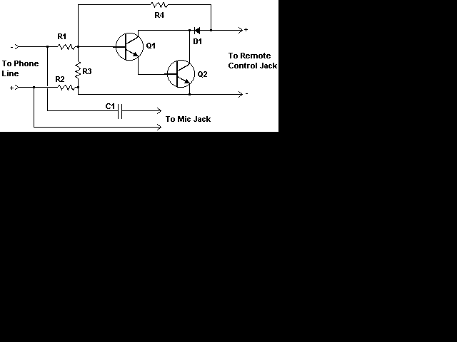
| This nifty little circuit lets you record your phone conversations automatically. The device connects to the phone line, your tape recorder's microphone input, and the recorder's remote control jack. It senses the voltage in the phone line and begins recording when the line drops to 5 volts or less. |
Schematic |
Parts |
|
Notes |
بازگشت به صفحه اصلی |
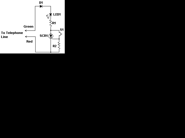
| Although a hold feature is standard on most new phones, a lot of us still use the origional bell phones. Those of us that require a hold feature will find this circuit very useful. It is easy to build, and is compact enough to be installed inside the phone with no real problem. It is also powered by the phone line itself, eliminating the need for batteries. |
Schematic |
Parts |
|
Notes |
بازگشت به صفحه اصلی
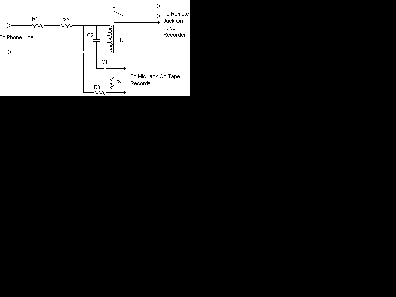
| This circuit is extremely simple, therefore there is less chance of any problems. It can be placed anywhere on the phone line and it will record any conversation on any phone on that line.
Please note: I have received several emails saying that this circuit will not work and that it may hold your line off hook and to me it looks like it will (it would put quite a load on the phone line). For some, it has worked fine. Build at your own risk. |
Schematic |
Parts |
|
Notes |
بازگشت به صفحه اصلی |
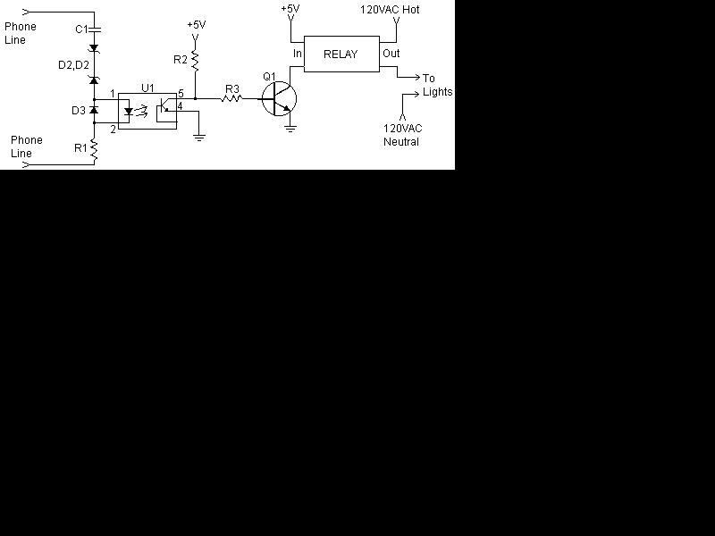
| I have received several emails asking how to connect up some lights so that when the phone rings, they flash. This is very useful in a situation were there is lots of noise and it is impossable to hear the phone, such as a workshop. Here is such a device. |
Schematic |
Parts |
|
Notes |
بازگشت به صفحه اصلی |
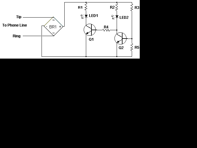
| Have you ever been using the modem or fax and someone else picks up the phone, breaking the connection? Well, this simple circuit should put an end to that. It signals that the phone is in use by lighting a red LED. When the phone is not in use, a green LED is lit. It needs no external power and can be connected anywhere on the phone line, even mounted inside the phone. |
Schematic |
Parts |
|
Notes |
بازگشت به صفحه اصلی |
| A while ago I got an email asking for the schematic of a circuit to detect cut phone lines. It didn't take me long to find this circuit in . When the circuit detects that a phone line has been cut, it activates a MOSFET which can be used to drive a relay, motor, etc. It can also be connected to a security system. |
Schematic |

Parts |
|
Notes |
بازگشت به صفحه اصلی |
| مدارات الکترونیک دانشمند |
Guitar and Bass Sustain Unit
We have all heard that wonderful sound of a guitar, where the note just hangs there seemingly forever (or at least until next Thursday). Sustain can be obtained by turning the amp up full, but the rest of the band will just kill you - they need to be able to hear themselves too! This little project is best used in the effects loop of a guitar amp (if it has one - not all do). It can be used direct from the guitar, but the effect is not as good, since it is designed for relatively high levels (around 1 Volt).
The circuit is very simple to build, and mine is on a piece of Veroboard. Because it can easily be built as a pedal or even into a guitar amp (such as that described in Project 27), I do expect to make PCBs available in the not too distant future depending on demand, and these may have a few additional functions as well.
The complete schematic is shown in Figure 1. There is not a lot to it, but the LED and LDR (Light Dependent Resistor) are critical - they must be completely enclosed in a light proof enclosure of some kind. Vactrol make some very nice little LDR opto-isolators, but unfortunately they are not easy to get, and are fairly expensive. The next best thing is a couple of pieces of black heatshrink tubing. The LED and LDR must be as close to each other as possible, and a flat topped LED is recommended if you can get one.

Figure 1 - Guitar and Bass Compressor
Note the rather unusual earth (ground) connection. This is not a mistake in the drawing. U2A is used to buffer the 1/2 supply voltage created by R3 and R4, and instead of using the 12V supply negative as earth, the output of U2A is used instead. This gives a balanced supply from a single voltage source. Note that the AC/DC adapter (plug pack or wall wart - select the term you are most comfortable with :-) must not be used to power other equipment as well, since this may cause problems. If you wish, a conventional +/-15V supply may be used instead, and U2A will not be used. Note that if a +/-15V supply is used, you must increase the value of R13 to about 3.3k to limit LED current to around 10mA.
All resistors are 1/4 or 1/2 Watt, and may be 1% or 5%. R1 and R2 should be metal film for lowest noise. Although the TL072 is suggested for the audio path, other opamps may be used as well. Likewise, the LM1458 can also be substituted if you like. Caps are 16V types, but higher voltage units can be used if desired. D7 is a power on indicator, and D6 is there to prevent damage to the circuit if the polarity of the applied 12V DC is incorrect. Be warned that the AC/ DC adapter will be damaged if the polarity is wrong, and it is left connected for any length of time.
VR1 is a simple volume control, and is used to set the output level. VR2 is the limiting threshold control - as it is adjusted to a higher setting, the volume will decrease. You may wish to wire the pot "backwards", so that maximum output is obtained when VR2 is set to the fully clockwise position.
U1A is the gain control stage. Maximum gain as shown is unity, but R2 can be increased if you find that the gain is too low. When the signal level is high enough for D1 - D4 to conduct, the LED illuminates, and reduces the gain of the input stage. Any further increase of input voltage will just cause the LED to glow brighter, which reduces the gain. In this way, a constant output level is maintained, since as the input signal reduces, so does the LED brightness and the stage gain increases again.
The connections shown will be fine for most purposes, but some LDRs may give distortion at low frequencies. A 100uF cap in parallel with the LED will probably help if this is a problem. LDRs typically have a slow "release" time. After illumination, they take some time to return to their full dark resistance. This characteristic is exploited here, to allow a very simple circuit with an almost perfect attack and release time for musical instrument use.
I have also used mine on music, and it gives a very good account of itself - so much so that I would recommend this unit as a simple compressor for almost any application.
بازگشت به صفحه اصلی |
| مدارات الکترونیک دانشمند |
Musical Instrument (Expandable) Graphic Equaliser
This equaliser is designed as a preamp suitable for musical instruments - guitar, bass and keyboard in particular. Unlike most conventional graphic equalisers, each slider ranges from fully off to fully on, and not the more conventional +/-12dB or so that is normally available.
As a result, there is no flat setting (other than all off!). This graphic is designed to be used to create a sound, and is not suitable for hi-fi. It may be used as an add-on unit to existing instrument amp preamps, tone controls, etc. The flexibility is extraordinary, allowing a hollow "single frequency" type sound, right through to almost any tonal variant imaginable.
This is the first of several projects based on the multiple-feedback bandpass filter described in Project 63, it can be made with as many (or as few) filter sections as you want.
Because of the repetetive nature of the filter units, I will be designing a PCB for them at some time in the future (depending on demand). One board will carry two or 4 filters, and the boards will be quite small so they can be packed into a case easily. The remainder of the circuitry can easily be constructed on Veroboard or similar.
The input circuit is completely conventional, and uses 1/2 of a dual opamp as the initial gain stage. This is followed by the volume control, second gain stage and buffer. The output of the buffer is fed to the inputs of the filter stages, each of which has a slider for its specific frequency. The outputs of the sliders are summed using another opamp, and a distortion effect is included in the final output stage. This can be left out altogether if distortion is not desired.
If used for guitar, the frequencies needed only have to range from 80Hz to about 7kHz, but to make the unit more versatile I suggest that the lowest frequency should be 31Hz, and the highest around 12kHz. This can be extended if you want.
Decisions!
Now you have to decide on the frequency resolution. 1/3 octave would be really nice, but the number of sliders can be a nightmare. At the very least, you will need octave band, and the suggested frequencies are ...
31 63 125 250 500 1k0 2k0 4k0 8k0 16k
Should you decide on 1/2 octave band frequencies, 20 sliders will cover the range suggested (plus a bit) - these might be ...
31 44 63 87 125 175 250 350 500 700 1k0 1k4 2k0 2k8 4k0 5k6 8k0 11k 16k 20k
The 20kHz filter can be (should be?) left off for instrument use, so that means only 19 slide pots will ne needed. Lastly, 1/3 octave band needs 30 sliders to cover the full frequency range, but the 25Hz and 20kHz bands will not be needed. This still requires 28 slide pots, but the flexibility is greater than you will ever get with conventional tone controls ...
31 40 50 63 80 100 125 160 200 250 315 400 500 630 800 1k0 1k2 1k6 2k0 2k5 3k2 4k0 5k0 6k3 8k0 10k 12k 16k
There is no reason at all that the unit has to be 1/2 octave or 1/3 octave all the way. The midrange can be 1/3 octave for finest control, but go to 1/2 octave at the extremes. Especially for guitar and bass, I would prefer 1/3 octave up to 1kHz, then 1/2 octave from 1kHz to 8kHz. The final slider would be a 1 octave band filter at 16kHz. The sequence now looks like this ...
31 40 50 63 80 100 125 160 200 250 315 400 500 630 800 1k0 1k4 2k0 2k8 4k0 5k6 8k0 16k
This gives 23 filters and slide pots, a reasonable compromise that should give excellent results. To ensure reasonable continuity, the filters at 1kHz and 8kHz will need to be a compromise. 1/3 octave filters need a Q of 4, and 1/2 octave filters use a Q of 3, so the 1kHz filter will actually have a Q of 3, and the 8kHz filter will be best with a Q of 2. This might look daunting, but the MFB Filter design program will make short work of determining the component values. Unfortunately, this is only available for users of Microsoft Windows. Note that you will also need the Visual Basic 4 (VB4) runtime library, which can be obtained from Annoyances.org (easy) or the Microsoft support Website (less easy).
If you want to use the frequencies shown above, the table at the end of this page shows the values for each filter.
The Circuit
Figure 1 shows the schematic of the input section, and is virtually identical to the guitar preamp presented in Project 27. The two input jacks allow rudimentary mixing of two sources, but are mainly designed to provide a high gain and a low gain input to help prevent input stage overload. The "Hi" input connects the signal directly to the opamp input, and the "Lo" introduces a 6dB loss to allow for high output pickups. The buffer stage has an effective load of about 810 ohms - a difficult load for an opamp to drive. I suggest that an NE5532 opamp is used for U1, as it is one of the few that can drive such a load without difficulty. Although a TL072 can be used, this should be for testing or as a last resort. Pinouts are the same for both types, but the NE5532 is more critical of supply bypassing, and the addition of 100nF ceramic caps from each supply to ground is strongly recommended (as shown). These should be as close to the IC package as possible.

Figure 1 - Instrument Equaliser Input Stage & Buffer
The filters and slider pots (with their mixing resistors) are shown in Figure 2. To see the actual filter circuit, refer to Project 63, it is far too cumbersome to draw each of these in full! Even so, only six of the 23 filters are shown. There is one filter module and one slider for each frequency. For guitar especially, you might want to provide more gain for the higher frequencies (typically from about 2kHz to 8kHz). No problem. Since the mixing resistors are nominally 100k, starting from the 1k4 slider, drop the value to 82k, then use 47k resistors for the remaining bands. This gives a 6dB increase in top-end boost which should be sufficient (you can have more, but this will increase the noise level).

Figure 2 - Filter Bank (Part), Slide Pots and Mixing Resistors
The filters do not need really quiet opamps, and considering the number this would be prohibitively expensive. The opamps do need to be at least to the standard of the TL072 or filter performance will suffer. The suggested frequency ranges will give good performance at all frequencies, since the Q (and hence the demands on the opamps) is reduced as the frequency increases.
Finally, the mixer and output stage are shown in Figure 3. The mixer is a conventional "virtual earth" type, and minimises interaction between the slide pots. The distortion stage uses the diodes (all 1N4148 types) as a clipping circuit, and in conjunction with VR24 (Master Volume) allows the amount of distortion to be adjusted from zero to 'heavy metal' (aka 'grunge'). It may be necessary to use more diodes than the 4 shown. An additional 4 diodes will raise the maximum output level to about 1,5V RMS before clipping starts. The final opamp is a buffer, and contributes no gain.

Figure 3 - Mixer and Distortion Circuits
A word of warning. Don't expect this preamp to be especially quiet, because it won't be. Use of a low noise opamp for the mixer helps, but as with all guitar amps, some noise is inevitable. This is made worse by all the filter circuits, but each only adds noise in its own band, so the cumulative noise is not as great as it might be. Using the distortion control will increase noise, and this can be dramatic at full distortion. In reality, this is not much different from a conventional guitar preamp that is turned up LOUD to get the same distortion. The more gain you have, the greater the noise (ye cannae change the laws of physics!).
Using the equaliser is simplicity itself. Just slide sliders up and down to get the sound you want. There is no "correct" way to use this unit - it is designed to enable you to get sounds. As described above, you can get more of any given frequency by reducing the value of the mixing resistor, but there is a limit to how much noise is tolerable.
The total gain of the unit (with all sliders at maximum) is about 15 times for the input stage, and a further 7.6 for the mixer (using all 100k resistors). This gives a total gain of 113 (or 41dB). Actual gain will be different, depending on the slider setting, and can be increased (or reduced) by changing the value of R33 (lower the value for less gain and vice versa) or R7 (lower value gives more gain). If you change the gain structure, be careful that the input gain is not made too high, or you will get distortion with high output pickups.
To power the circuit, any power supply capable of +/-15V (+/-12V at a pinch) will do, provided that it is capable of 100mA or so.
The table shows the values I calculated for each filter. Component references are based on the diagram in Project 63, which is reproduced here for convenience (pin connections are shown for a single opamp). For this application, omit C3, R4 and short the non-inverting opamp input to ground.

Figure 4 - Multiple Feedback Bandpass Filter
| Freq | R1 | R2 | R3 | C1, C2 | Freq | R1 | R2 | R3 | C1, C2 | |
| 31 | 82k | 2k7 | 160k | 220nF | 500 | 27k | 820 | 56k | 47nF | |
| 40 | 82k | 2k7 | 160k | 180nF | 630 | 27k | 820 | 56k | 39nF | |
| 50 | 82k | 2k7 | 160k | 150nF | 800 | 27k | 820 | 56k | 27nF+2n7 | |
| 63 | 82k | 2k7 | 160k | 120nF | 1k0 | 8k2 | 510 | 18k | 47nF+4n7 | |
| 80 | 82k | 2k7 | 160k | 100nF | 1k4 | 8k2 | 510 | 18k | 39nF | |
| 100 | 82k | 2k7 | 160k | 82nF | 2k0 | 8k2 | 510 | 18k | 27nF | |
| 125 | 82k | 2k7 | 160k | 56nF+5n6 | 2k8 | 8k2 | 510 | 18k | 18nF+1n5 | |
| 160 | 82k | 2k7 | 160k | 47nF | 4k0 | 8k2 | 510 | 18k | 12nF+1n8 | |
| 200 | 82k | 2k7 | 160k | 39nF | 5k6 | 8k2 | 750 | 18k | 8n2 | |
| 250 | 82k | 2k7 | 160k | 27nF+4n7 | 8k0 | 8k2 | 1k2 | 18k | 4n7 | |
| 315 | 82k | 2k7 | 160k | 22nF+2n7 | 16k | 8k2 | 1k2 | 18k | 2n2 | |
| 400 | 82k | 2k7 | 160k | 18nF+1n5 |
I have tried to keep the values reasonably sensible. This is not easy with 1/3 octave band equalisers, but all in all the results are quite acceptable (not too many different values). Note that the Q of the filters is changed as the frequency increases - feel free to use the calculator to reverse calculate the values to see the actual gain, Q and frequency error. None of these will be significant in use.
بازگشت به صفحه اصلی |
| مدارات الکترونیک دانشمند |
Introduction
Using a compressor (or to be more correct, a peak limiter) on bass guitar is one sure way to get more apparent volume, without distortion. A good bass compressor will often have a relatively slow attack, so that you get a very solid "chunky" start to each note, with lovely sustain and equal volume for all notes (speaker box allowing, of course).
The project described here is one that you can just build and have working straight away (although it is entirely possible that you will want to experiment a bit), and requires only a small handful of parts. In its simplest form, there are no active electronics at all - and this is exactly what is described.
In case you were wondering, it can also be used with guitar, and can give excellent sustain, although this circuit is too slow to give perfect results.
The way a compressor / limiter works is quite simple. Once the preset threshold has been reached, the gain of the amplifier is reduced to maintain the output at the preset level. As the signal decays, the gain is allowed to increase again to compensate, until the amp is at full gain and the signal then dies out naturally.
The unit described here uses a light dependent resistor (LDR) and a small light globe, of the type commonly referred to as a "grain of wheat". These are very small, and having a small filament, they react quite quickly to an applied signal. LDRs have a very high resistance when dark, and this falls as more light is received. Typical LDRs will have a dark resistance of several megohms, and a minimum resistance of about 200 ohms or so. The distortion introduced is very slight (typically less than 0.5%), especially at low levels.
Now, if the lamp were to be placed across the speaker output of your amp, and its light shines on an LDR, as the light gets brighter, the LDR will have less resistance. The LDR is arranged in the circuit to form a voltage divider, so that as the resistance decreases, the input level is reduced, and a simple limiter is operational.
The problem with this approach is that the lamp will start to glow brightly enough to reduce the input signal with only a few volts of speaker output, so the level will be very low - with only a few watts of speaker drive. This is fixed by using a wirewound pot across the speaker terminals, so that the amount of output signal getting to the lamp can be varied. In this way, the output level is set by the pot, and the amount of compression is set by the amplifier's volume control. Figure 1 shows the complete circuit.

Figure 1 - Simple Bass Guitar Compressor
The pot will need to be rated at 3W, and with a 500 Ohm pot, it can be used with amplifier powers up to a bit over 150W into 8 Ohms (or 300W into 4 Ohms). It is very important that the input section is properly shielded, otherwise the amplifier may oscillate, and the lamp and LDR must not be placed too close together for the same reason.
Ideally, you will use a small piece of clear Perspex rod, with a hole drilled into one end to take the lamp. The LDR is then glued to the other end using a transparent adhesive (model glue is ideal). Figure 2 shows the suggested method of assembly, which will ensure that you don't have problems with oscillation from the amp. Don't glue the lamp in place, as you will probably have to replace it at some time or another. These little lamps normally will last a long time in this sort of circuit, but they will eventually fail, so keep a spare in the box. You might want to connect the lamp using a small screw-down terminal block, so that a replacement can be made without having to use a soldering iron.
When the light pipe is completed, wrap the LDR end with aluminium foil, and tightly twist a bare wire around the foil to make good contact. Tape the assembly firmly so that nothing comes undone. This acts as a shield, and is connected to the earth (ground) connection on the input jack. Make sure that the foil does not short circuit the LDR leads, or you will get no signal at all. Note that one of the LDR leads will be connected to ground anyway - it does not matter which one.

Figure 2 - Assembly Of The Compressor
The complete unit should be housed in a metal box that is completely light proof. Any ambient light that penetrates the box will affect the LDR, and will either introduce hum or cause greatly reduced performance (or both). The die-cast aluminium boxes available from many retail electronics suppliers are ideal, as they are very robust, and provide excellent shielding.
Make sure that the speaker connectors are of the insulated type, because some amplifiers do not use earth referenced outputs. Failure to ensure that these connectors are properly insulated may damage the amp or cause the amp to oscillate. Also make sure that the speaker leads are kept well away from the input connectors. If necessary, a shield may be made from thin metal and used to separate the two halves of the circuit.
Using The Compressor
Plug the bass directly into the input, and another lead from the output to the input on the amp. Plug a spare speaker lead into the speaker input (or run a lead from the amp to the Speaker In jack, and another from the Speaker Out to the loudspeaker. The speaker sockets are completely interchangeable, so you can use either for In or Out. The Input and Output jacks are NOT interchangeable, although the circuit will still seem to work (just not as well, and the tone will go all funny as the LDR loads down the pickups).
Set the 500 Ohm pot fully off, and play a note or three. Once you are satisfied that all is well, turn the pot to maximum, and increase the volume a little. When you play a note, there should be a solid attack, and then the level should quickly stabilise, but at a greatly reduced volume. You will find that you can get really good sustain, and you simply play about with the compressor pot and the amp's volume control to get the sound you want at the volume you need. The apparent loudness will increase (often by a large margin) because the amp can be consistently driven harder, but will not distort. You will get some distortion during the attack period, but (surprise) this can often be used as a sound in itself, and is not unpleasant because of the short duration.
So, there it is. Not much electronics, but more of an exercise in construction. It works surprisingly well, and I think you will have lots of fun with it. The attack time is a wee bit long for guitar, but the sound is not unpleasant, and you can also increase the gain (a lot!) and get amazing sustain with minimal distortion.
بازگشت به صفحه اصلی |
| مدارات الکترونیک دانشمند |
Spring Reverb Unit For Guitar or Keyboards
Updated 17 November 2006
Well, its not really just for guitar or keyboards, you can use it for anything that you want. Spring reverb units are most commonly used in guitar amps, having been replaced by digital effects in most other areas. This cannot really be classed as a "real" project, because the circuitry is somewhat experimental, and may change quite dramatically depending on the type of spring reverb unit you can actually get your hands on.
The one I have is an Accutronics (they are still going, so check out their web site - see below), but you might already have one, or can get something different, so you will have to experiment.
Most of the possibilities are discussed here, so with a small amount of mucking about you should be able to create a reverb unit tailored to your exact needs. For additional information, see the end of this page.
Since the P113 headphone amp is very easily modified for constant current drive, this is recommended. The circuit diagram in Figire 3 is the original, but it does have limitations. The main limit is the allowable voltage swing, but this is overcome by using the P113 board with appropriate modifications (all described in the construction article).
The basic spring reverb chamber is a simple affair (see Figure 1), with an input and output transducer, and one or more (usually three or four) springs lightly stretched between them. Each spring should have different characteristics, to ensure that the unit does not simply create "boinging" noises. Stay well clear of single spring units, they are usually cheap Taiwanese affairs and can often found in really cheap guitar amps. They sound awful, and nothing you do will ever change this. This is not to say that the Taiwanese don't make decent spring reverb units too, I just haven't seen one yet.

Figure 1 - Basic Spring Reverb Unit
Many reverb units appear to have only two springs, but you will see that there are joins in the middle. This is where two springs are joined, and each spring should be very slightly different. Ultimately it doesn't matter how many springs they really have, a spring reverb always sounds like what it is. This is not a criticism, merely a description of the sound.
Of the units around, most of the newer ones have a low impedance (about 8 Ohms) input transducer, and are well suited to being driven with a small power amp IC. The one I have has a relatively high input impedance (173 Ohms DC resistance, and according to the specs, about 1700 Ohms impedance), but the principles are still pretty much the same.
Another common type of reverb tank (common terminology, BTW), is the folded spring type. These have the springs arranged in a Z pattern and sound quite good. They have been used by some very well known guitar amp manufacturers.
In all cases you will need a small power amp to be able to drive the unit properly, but you must be very careful, because overdrive causes the small pole piece to become magnetically saturated, leading to gross distortion that increases with decreasing frequency. One solution to this is to use a series resistor to reduce the drive and give a higher output impedance from the amp. This usually improves frequency response, especially at higher frequencies, but tends to disappear the bottom end. This is not always a bad thing, since in reality low frequency reverberation in a typical room or auditorium is rare, and generally sounds awful when it does exist.
Another possibility is to use an amplifier with a high output impedance, but this is not necessary because of the very low power handling of the input transducer. As a result, I suggest the series resistor method, as this is the easiest to implement, and helps to protect the transducer from gross overloads. The basic scheme is shown in Figure 2, and has the added advantage that modification to the reverb unit is not needed (many (most?) have the earth of both input and output transducers connected to the chassis - to use a current amp, this would need to be changed).
Using current drive is explained (see additional info, below) and I have used it and it works well. The problem is that it makes the reverb very "toppy", with very little bass at all. While this might suit some players, I prefer a modified current drive, where the output impedance is defined (rather than "infinite") because you can tailor the sound to your liking much more easily. This is a little tricky with the small power amp ICs though. If you want more information on this, send me an e-mail - if I get enough interest I will work something out.

Figure 2 - Reverb Input Transducer Drive Amp
I have seen quite a few reverb drive amps used in other circuits, including just an opamp. Opamps do not have sufficient current capability to drive the input transducer properly, and even some of the small power amp ICs are a pain. The circuit shown has good drive, low current drain and works well. Most of the circuits I have seen also do not make any attempt to obtain current drive, and use the low impedance output from the drive amp. This is not the best way to drive these transducers, and the method shown works much better.
The resistor marked S.O.T. (Select On Test) will need to be selected to provide the best reverb sound, with the minimum voltage loss. I suggest a starting value of about 47 Ohms (depends on the input transducer's impedance), and experiment from there. The positive voltage needs to be not less than 15V (18V is the rated maximum) to be able to get good drive levels with a high enough value of series resistor. In a pinch you might be able to get away with 9V, but you will not have much drive level and will need more gain at the output. This increases noise and the possibility of feedback.
The output transducer will have an output of (typically) about 10mV, and a gain of 10 (20dB) is usually enough to match the output of the guitar. It is an easy matter to increase this if you want to. The circuit shown uses 1/2 of a NE5532 low noise opamp (a TL072 can also be used, but with a noise penalty) - this is quite adequate for what we need here.
With the values shown, the gain is variable from unity up to a maximum of about 40dB (22 times), which should be enough for anyone. ("640k of RAM should be enough for anyone" - Bill Gates  ).
).
The complete circuit is shown in Figure 3, with a reverb mute switch and level controls. The drive control (VR1) can be a trimpot (or even fixed), since once you have determined the maximum level this will not need to be changed. There is no gain control for the guitar input, as the circuit has unity gain, so amp settings are unaffected by using the reverb.
The capacitor marked S.O.T. will need to be selected to give the sound you want. High values (above 100nF) will give quite a lot of bottom end, which tends to sound boomy and very indistinct. You will probably find that a value somewhere between 1.5nF and 10nF will sound the best - try 4.7nF as a starting point. Like the guitar amp itself, a reverb unit has its own sound, and it is only reasonable that you should be able to change it to suit your own taste.

Figure 3 - Complete Circuit
The power for the opamp is, Pin 4 -ve, Pin 8 +ve. Note that the opamp requires a dual supply - +/- 15V is fine, or for battery operation (not really recommended) you could get away with ±9V.
The unit could also be installed inside the amp head, and wired into the circuit. I will have to leave it to you to determine the gain needed for the various stages, since it is currently designed for "typical" guitar levels. Make sure that you provide proper isolation between the input and output of the reverb tank. I have seen circuits where this was not done, and the whole reverb circuit goes into feedback. Isolation is provided in this circuit by the virtual earth mixer (pin 2 of U1 is at 0 Volts at AC and DC).
Most reverb units use RCA sockets for input and output, and be careful with mounting. The springs will clang most alarmingly if moved about while playing, and acoustic feedback can also be a problem, especially if the low frequency gain is too high.

Figure 4 - Modified Version, Using P113 Headphone Amp PCB
The version shown in Figure 4 uses the drive amp configured for high output impedance. Maximum input level depends on the gain of the drive amp, which is controlled by R3L. The optimum value depends on the impedance of the reverb tank's input impedance. As shown, it is optimum for a (nominal) 160 Ohm coil. Note that the input transducer must not connect to the tank chassis. Reverb units are available with isolated inputs for just this purpose.
The recovery amp has a gain of 40 as shown (32dB), but this can be changed by using a different value for R3R (lower value, higher gain).
Torres Engineering - Supply and information on spring reverb tanks
Roy's "Accutron" Page - Some more useful info.
Almost all the reverb tanks that you will see are Accutronics (aka Sound Enhancements). They are made by:
بازگشت به صفحه اصلی |

| مدارات الکترونیک دانشمند |
Tremolo is one of those simple effects that has just lasted forever (well, almost). The circuit shown here has wide range, and a very controlled and musical modulation characteristic, and should keep the guitarists happy for minutes at a time.
The project is simple to build, and can even be housed in a pedal if desired. If the pedal option is used, don't try to run it from batteries, as they will not last very long due to the LED current. It really needs a +/- 15V supply as shown in the circuit to operate properly.
The unit is simple to build, and does not need really low noise opamps, since they only act as a modulator oscillator. I used 1458 dual types in the prototype, and they are more than good enough. The transistors can be any low noise NPN type, and they are simply buffers, ensuring a high input impedance and low output impedance.
If the unit is to built into an amplifier, it may well be possible to leave out the input transistor, since a low impedance drive circuit is probably already available from an existing opamp. It may also be possible to leave out the second transistor if a high impedance input is available at the insertion point. This is somewhat unlikely, since the most common place to have the modulator is before the tone controls.

Figure 1 - Tremolo Unit Circuit
The opamp power supply pins are: Pin 4, -ve and Pin 8, +ve. This is the same on virtually all dual opamps. The value of C2 might need to be changed (in some cases it can be omitted) if the load impedance is less than about 20k Ohms.
The oscillator is a simple opamp feedback type, and produces a triangle wave from the capacitor (C3). This is amplified and buffered, and fed to the LED in the opto-coupler. If you are unable to obtain this device (made by Vactrol), use a high quality Light Dependent Resistor (LDR) with a LED in a light-proof encapsulation - heat-shrink tubing is good, but you will probably need two layers to ensure it is completely sealed against light getting in. Use a high output LED, and make sure that the LED and LDR are properly aligned for maximum sensitivity.
The second LED is used as a panel indicator, and can be any colour you choose. When switched off, the LEDs will both be off, and the panel LED flashes at the selected rate. It might be necessary to reduce the value of R10 to ensure that there is enough drive to the LEDs to get the full modulation.
The frequency range is from about 2.5Hz to 14Hz with the values as shown, but this can be changed to suit your needs. This is generally a good range, and will be more than wide enough for most users.
Amplitude modulation can be varied from none at all, to full modulation with the signal varying from fully on to fully off. The frequency range that can be covered with full modulation is dependent on the speed of the LDR. Most of the commonly available ones are fast enough to give a good modulation depth at even the highest frequency.
بازگشت به صفحه اصلی |


